Period counter using delay
This example shows a 1Hz period counter using Unit Delay in
QFIRE Studio
.Introduction
When the input signal is logic high, the counter must increment by one. Otherwise, reset the counter. But, if the counter reaches the maximum it shall stop incrementing until reset.
Simulation
As a test input signal, a unit step happens until 8s. It is modeled as in Figure 1.
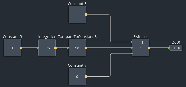
Figure 1 - Diagram of the test signal
Figure 2 shows the counter diagram:
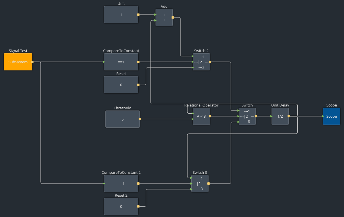
Figure 2 - Diagram for the logical conditions required
When the count value is lower than the threshold, the Unit Delay block receive the signals from Switch 2, otherwise it receives signals from Switch 3. Its behavior can be detailed as follows:
- The orange block contains the diagram from Figure 1. The counter uses the Unit Delay Block, which acts as a feedback. At each step, the counter value in the block is updated.
- Switch 2 controls increment (input high) or reset (input is low). It works only when the count is lower than the maximum. In this example, de maximum value is the threshold value of 5.
- Switch 3 limits the maximum value of the counter or resets the counter when input is low. Unlike switch 2, switch 3 works when the count reaches the threshold value.
- The output of these two switches are managed by another switch connected to the Relational Operator.
The test input signal modeled in Figure 1 generates the signal in the following graphic:
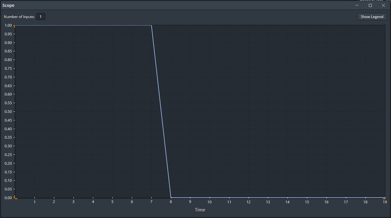
Figure 3 - Test signal (unit step until 8s)
And the the count value for this simulation is represented by the following graphic (increments when input is high, decrements when input is low, and is bounded between 0 and 5):
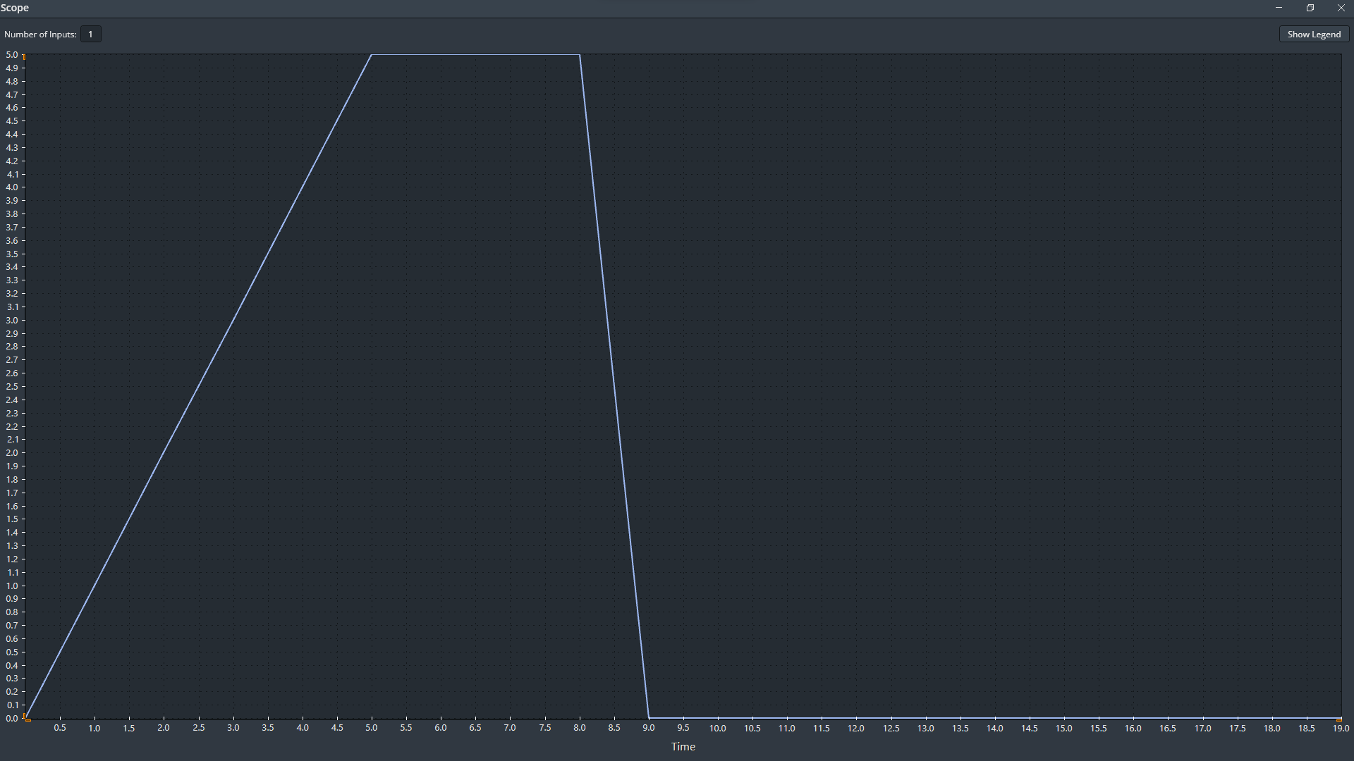
Figure 4 - Counter output signal
At the time of 4s, the counter reaches the threshold value and holds it until the time of 8s. The counter resets when the input signal becomes low at 8s.
About MWF
MWF is a traditional Brazilian company that provides a wide range of electronic and mechatronic products for industry sectors such as automotive, agricultural machinery and aerospace.
Contact Us
Rua Doutor Siqueira, 139 / Sala 804 Campos dos Goytacazes - RJ, Brasil
contact@mwf-technologies.com
© 2018-2026 MWF. All rights reserved.